Wiring Guide
This guide walks through the most common things you'll wire to an Output 8 MKII. For everything covered here, Easywire™ can light up the right terminals on the controller and walk you through it visually — these instructions are the manual fallback.
Photos coming soon. The wiring procedures below are accurate; we're working on diagrams to match.
We know wiring is intimidating the first time. If anything below is unclear, jump on Discord — someone in the community has wired exactly the thing you're wiring.
The Connector Config
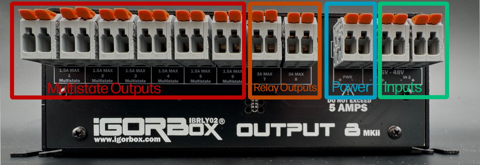
Each channel is a WAGO connector starting with channel 1 on the left and going to channel 8.
The first 6 WAGOs are Multistate relays and can function as normal relays or solid-state-like relays.
When in normal (relay) mode they are just shorting together when active. In this mode the connector pair lights GREEN: both bright when the channel is on, with one light keeping a faint marker glow when it's off. If you switch to solid-state mode in the software, they become switched power (internally jumped to the power) and the pair lights RED and BLUE instead, matching the power-terminal colors: red marks the positive terminal and blue the negative, bright when the output is live and faint when it's off. These are limited to a max of 1.5A each. See Indicator Lights for the full rear-panel light reference.
The next 2 WAGO connectors are standard "high power" relays capable of 3A sustained.
The next WAGO (after channel 8) is the Power Output which is fed by the barrel jack you plug into the front of the controller. Positive is left and Negative is right. The helper LEDs indicate Red for Positive and Blue for Negative to help you identify this connector as well.
Then the last two WAGOs on the right are Input 1 and Input 2 for triggering shows in your system or using in logic rules.
The polarity of the inputs is not relevant as they can be wired in any polarity and support 6–48V DC or AC.
Channel basics
Every output channel is a vertical pair of WAGO terminals:
- Off — the two terminals are not connected.
- On — the two terminals are connected. Power flows through the load.
Treat each channel like a light switch in the load's positive (V+) leg.
Wiring a light
- Connect the power supply's GND to the light's GND.
- Connect the power supply's V+ to one terminal of an output channel.
- Connect the other terminal of that channel to the light's V+.
When the channel turns on, the light turns on. When it's off, the light is off.
Using the passthrough power
If the light runs off the same voltage as the controller (12V or 24V DC), you can save a power supply by jumping power from the center passthrough zone to the channel:
- Connect the light's GND to the GND terminal in the passthrough zone.
- Jump V+ from the passthrough zone to one terminal of an output channel.
- Connect the other terminal of that channel to the light's V+.
The passthrough is the same voltage as your input supply and shares its rails with the controller. The internal bus is rated for 2A total. If you're powering more than 2A worth of loads, use an external supply for the loads.
Wiring a pneumatic solenoid
Pneumatics are wired exactly like a light, but pay attention to current and voltage:
- Most show pneumatic solenoids are 12V or 24V DC.
- Coil current at hold is usually under 1A.
- Inrush current at the moment of latching can spike to 2–3× the hold current.
For a typical 24V monster valve (~0.5A hold), a Multistate channel in relay mode is fine. For a heavier valve (>1A hold or >2A inrush), use channel 7 or 8 (the 3A standard relays).
Pneumatic solenoids are inductive. Use a flyback diode across the solenoid's coil if it doesn't have one built in. Most show valves do; check your spec sheet.
Wiring a powered load in solid-state mode
Solid-state mode is the canonical choice when the load runs on the same DC voltage as the controller and you'd rather not run a separate power feed to the channel. Instead of switching a contact, the channel passes the controller's own supply through to the output — so the output is already live when it turns on.
- Set the channel to solid-state mode in Studio (Configuration tab → click the channel → Mode: Solid-state).
- Connect the load's GND to the GND terminal in the passthrough zone.
- Connect the load's V+ to the channel's output terminal.
When the channel turns on, the controller's supply voltage reaches the load — no jumper from the passthrough zone to the channel, and no second power supply.
Solid-state mode is DC only and outputs the controller's supply voltage (whatever you feed the barrel jack). It still switches ON/OFF — it does not dim. Don't wire an AC load to a solid-state channel.
The same 2A total internal bus limit applies: solid-state channels draw from the controller's supply, so everything powered this way shares that budget. For heavier loads, switch them in relay mode with an external supply instead.
Wiring a motor (heavy duty, ON/OFF only)
A wiper motor or other high-inrush motor needs the bigger relays:
- Use channel 7 or 8 (the 3A standard relays).
- Use an external power supply for the motor — don't pull motor current through the controller's passthrough.
- Wire it like a light: GND to GND, V+ through the channel.
Don't power motors from the controller's barrel jack passthrough. Motor inrush will brown out the controller and may damage components.
Wiring an input
The two inputs on the right side of the terminal block are isolated and accept 6–48V AC or DC. They're polarity-insensitive — you can't wire them backwards.
To use a button or footswitch:
- Connect the input voltage source's V+ through the button to one terminal of an input channel.
- Connect the input voltage source's GND to the other terminal.
When the button is pressed, the input fires, and its connector lights jump from a faint purple glow to bright purple (firmware 2.2.0 and later), so you can confirm the wiring right at the box. The inputs feed straight into the Logic Rules engine and can be used as triggers.
What about mains power?
We do not recommend or support running mains AC voltage through any IgorBox controller.
If you need to switch mains, use a show-control-grade relay panel wired to one of the IgorBox's outputs. The IgorBox switches a low-voltage signal that drives the panel; the panel switches the mains.