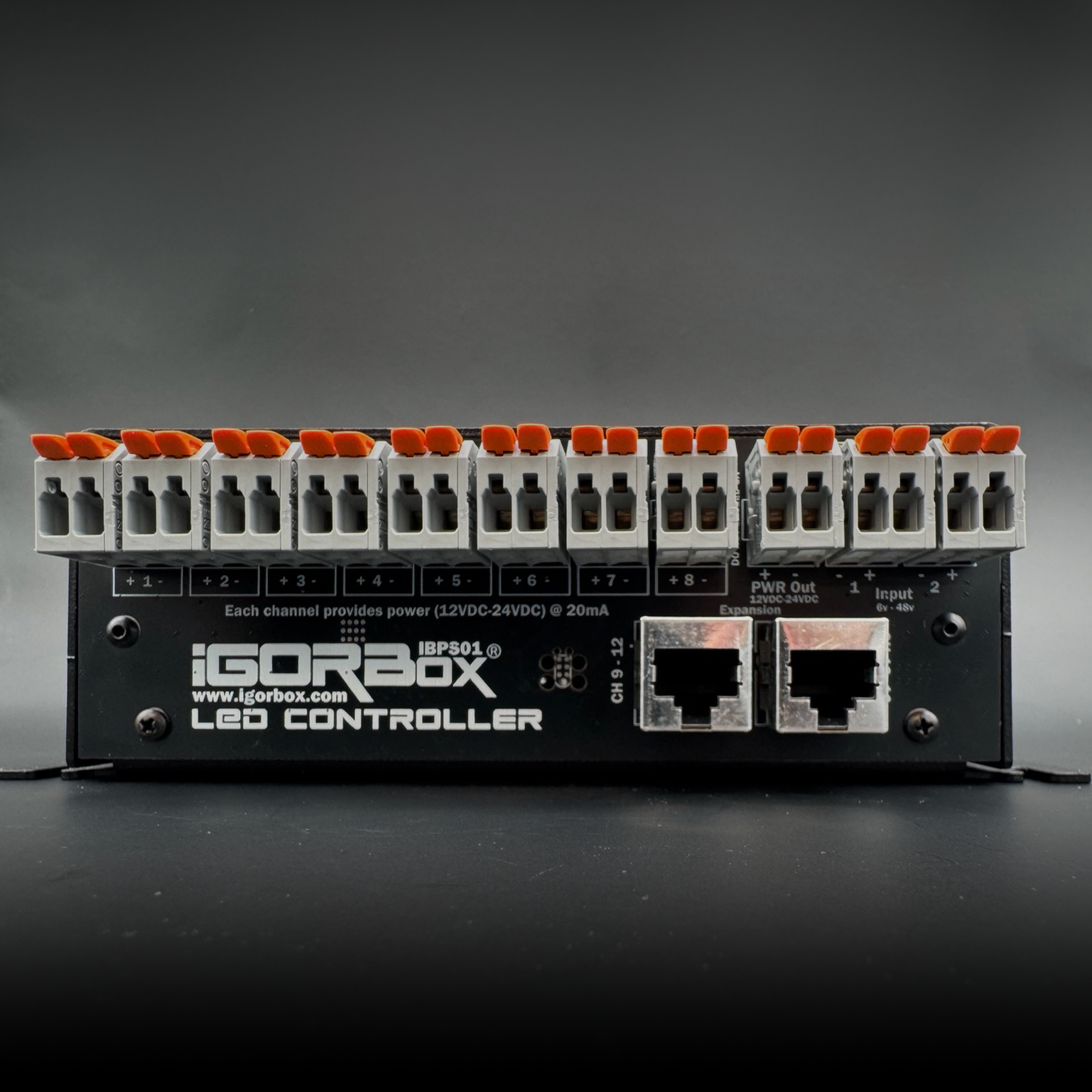
LED Controller
The LED Controller is a 16-channel low-current dimmable controller. Each onboard channel is a smooth dimming output, perfect for low-current LED loads — puzzle-board LEDs, signal indicators, panel lights, pinspots, low-power "puzzle solved" lights — or for driving an external power stage that does the heavy switching.
For higher-current loads — LED strips and larger fixtures — pair it with the RGBW-PWR breakout. The breakout adds a power stage so four channels can drive up to 120W of lighting per board.
It also has two isolated inputs you can wire into Logic Rules just like any other input.
What's in the box
| Outputs | 16 × dimmable channels (low current — clamped at 20 mA per channel) |
|---|---|
| Inputs | 2 × isolated inputs (6–48V AC/DC) |
| Voltage | 12V or 24V DC (selected during provisioning) |
| Connectivity | Ethernet + WiFi |
| Connectors | WAGO® on every terminal |
| Audio | Stereo line out (3.5 mm) |
| Storage | 32 GB onboard |
| Front panel | Status LED, RGB channel indicators, configurable front button |
| Power | 9–24V DC, center-positive barrel jack (12V 1A supply included) |
| Expansion | RGBW-PWR breakout — higher-current / different-voltage output for 4 channels, up to 120W per board |
| Channel breakouts | Channels 9–16 ship on two included breakout boards, connected by a standard Ethernet cable |
What 20 mA means in practice
Each onboard channel can drive up to 20 mA. That's enough for:
- A single indicator LED (the 5 mm or SMD kind on a circuit board)
- A panel light or pinspot — they're low-current LEDs too
- A solid-state relay's input
- An optocoupler that drives a downstream high-current circuit
- A low-power signal to another show controller
It's not enough for:
- A length of LED strip
- A larger fixture
- A motor
For those, use the RGBW-PWR breakout. The breakout takes the LED Controller's signal and drives the actual load with substantially more current.
Best for
- Escape room puzzle boards — sixteen indicator LEDs that flash, fade, and reveal solved puzzles
- Status indicator panels — visual readouts of show state for staff
- Driving external power stages — the LED Controller's channels are exactly what an SSR or breakout board wants on its input
- Real lighting — paired with the RGBW-PWR breakout (LED strips and larger fixtures, up to 120W)
- Motor speed control — paired with the RGBW-PWR breakout or an external motor driver
Quick start
- Power it up. 9–24V DC.
- Set the channel voltage. During Magic Provisioning, Studio asks whether the channels are wired for 12V or 24V loads. This is per-controller, not per-channel.
- Connect to the network. See Connectivity.
- Wire your channels with Easywire™ or follow the wiring guide.
- Build a show. Lighting is the place to start.
See also
- Wiring Guide
- RGBW-PWR Breakout — the accessory for real lighting and motor loads
- Motor Speed Control
- Channel Breakout Boards
- Front Panel
- Tech Specs
- Regulatory Compliance — FCC & ISED statements