Wiring Guide
The LED Controller's sixteen channels are dimmable DC outputs, each clamped at 20 mA maximum. That makes them perfect for:
- Indicator LEDs and other low-current LED loads (panel lights, pinspots)
- Solid-state relay (SSR) inputs — for switching bigger or line-voltage loads
- Driving the RGBW-PWR breakout for real lighting
Low-current LED loads — indicator LEDs, panel lights, pinspots — wire straight to a channel. For loads that pull more than the channel's 20 mA — LED strips, larger fixtures, motors — you'll want the powered RGBW-PWR breakout, which adds its own power supply. The instructions below cover both.
Easywire™ walks you through every wiring recipe visually.
The Connector Config
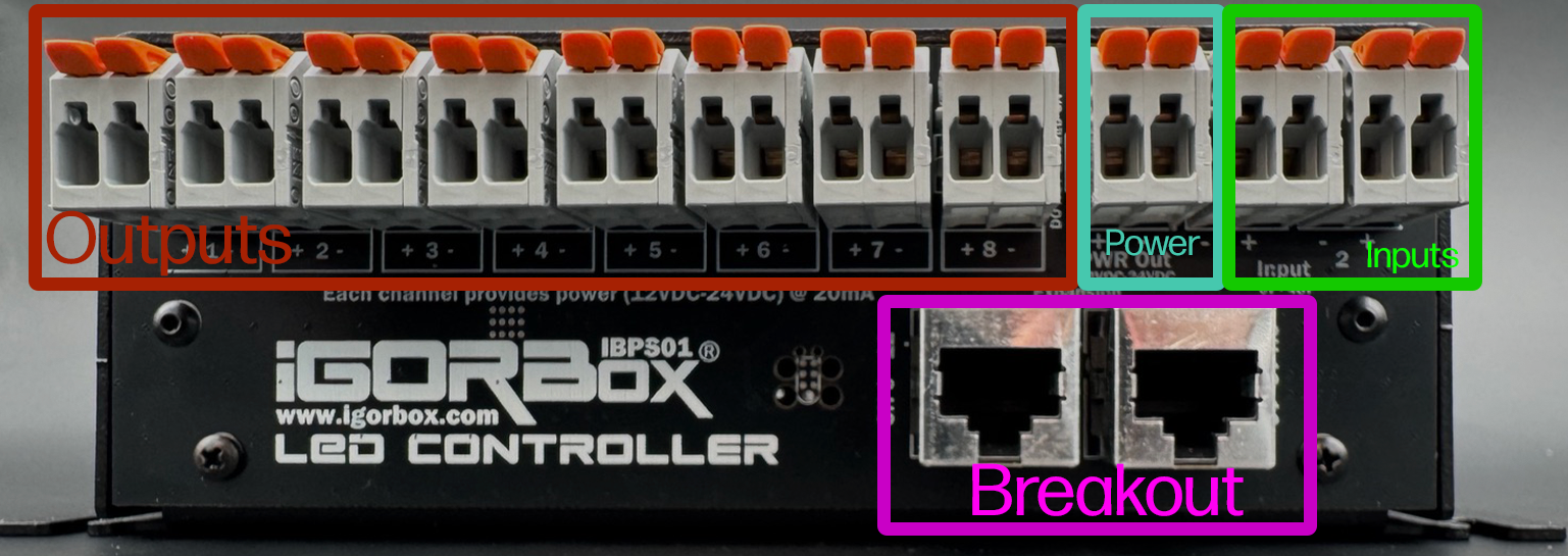
Each channel is a WAGO connector starting with channel 1 on the left and going to channel 8. Each WAGO has positive (+) on the left and negative (-) on the right for each channel.
Positive (V+) is always on and the Negative (V-) is switched on and off. This is the opposite polarity convention from the Output 8. On the LED Controller, you bring V+ from your power supply to the load's V+, and the controller switches the GND/negative leg of the load. This supports the way standard LED panels and strips expect channel switching to work.
The next WAGO (after channel 8) is the Power Output which is fed by the barrel jack you plug into the front of the controller. Positive is left and Negative is right. The helper LEDs indicate Red for Positive and Blue for Negative to help you identify this connector as well.
Then the last two WAGOs on the right are Input 1 and Input 2 for triggering shows in your system or using in logic rules.
The polarity of the inputs is not relevant as they can be wired in any polarity and support 6–48V DC or AC.
Under the row of WAGOs, you'll find 2 RJ45 jacks (Ethernet jacks). The left one is channels 9–12 and the right one is channels 13–16. Each jack connects to a channel breakout board. Two standard breakout boards ship in the box (one per jack) and carry the same 20 mA-clamped channels — a positive and a PWM-switched negative for each of the bank's four channels. To drive real lighting power on a bank, swap its standard board for the upgraded RGBW-PWR breakout, which brings its own power supply. See Channel Breakout Boards.
Wiring an indicator LED, panel light, or pinspot
Indicator LEDs, panel lights, and pinspots are all low-current LED loads — wire them the same way, straight across the channel:
- Connect the LED's anode to the channel's (+) terminal.
- Connect the LED's cathode to the channel's (-) terminal.
When the controller dims the channel up, the light brightens. The channel's (+) terminal already carries V+ from the controller, so you don't need a separate supply — and because the channel is clamped at 20 mA, you don't need a series resistor either: the load can't pull more than its safe current.
Channel voltage selection
The controller's channels operate at the voltage you run your IgorBox controller with - 12V or 24V. Mixing channel voltages on a single controller isn't supported; if you need both, use two LED Controllers or use an RGBW-PWR breakout to inject the other voltage.
Wiring an LED strip or larger fixture — use the RGBW-PWR breakout
For loads that draw more than 20 mA — LED strips, large fixtures — don't wire the load to a 20 mA channel (onboard or on a standard breakout). The clamp will limit how bright it gets, and the channel can't deliver the current the load wants.
Instead, use the RGBW-PWR breakout in place of the standard breakout on that bank. It has its own power supply, so it drives the actual lighting load with real current. From Studio's perspective, RGBW-PWR channels look just like onboard channels — same envelopes, same dimming, same UI.
Wiring a solid-state relay or other power stage (Bring your own power injector)
A solid-state relay (SSR) is an electronic on/off switch with no moving parts. You feed it a small control signal on its input side, and it switches a much bigger load on its output side — mains lighting, a large motor, or other line-voltage gear. Think of it as a silent, fast relay that a low-current channel can drive directly.
An SSR needs only a tiny amount of current to switch, so the LED Controller's channels are sized exactly right to drive one:
- Connect the SSR's control input + to the channel's (+) terminal.
- Connect the SSR's control input − to the channel's (-) terminal.
- Wire the SSR's output side to whatever you're switching (lights, motors, line-voltage gear).
Now the channel drives the SSR's control input from your timeline, and the SSR switches the real load to match. Other boards that take a low-current control signal — a motor driver's input, say — wire the same way.
Wiring the inputs
The two inputs follow the same conventions as the inputs on the Output 8 MKII and Input 16. They're isolated, polarity-insensitive, and accept 6–48V AC or DC.
To use a button or sensor:
- Connect the input voltage source's V+ through the button to one terminal of an input channel.
- Connect the input voltage source's GND to the other terminal.
The inputs feed straight into Logic Rules and can trigger anything in your show.
What you should not wire
- Lighting loads over 20 mA, directly to a channel — use the RGBW-PWR breakout.
- AC loads — the channels are DC only.
- Above the channel voltage — running 36V on a 24V controller will damage the channels.
- Mixed-voltage loads on the same controller without an RGBW-PWR breakout injector.