Wiring Guide
Every input on the Input 16 is isolated. That means there's no shared ground between your input voltage and the controller — wire something backwards and the worst that happens is the input doesn't read. Polarity-insensitive AC or DC, 6 to 48 volts.
The two relay outputs (1.5A each) follow the same wiring conventions as the relay channels on the Output 8 MKII.
Easywire™ walks you through every wiring recipe visually. The instructions below are the manual fallback.
The Connector Config
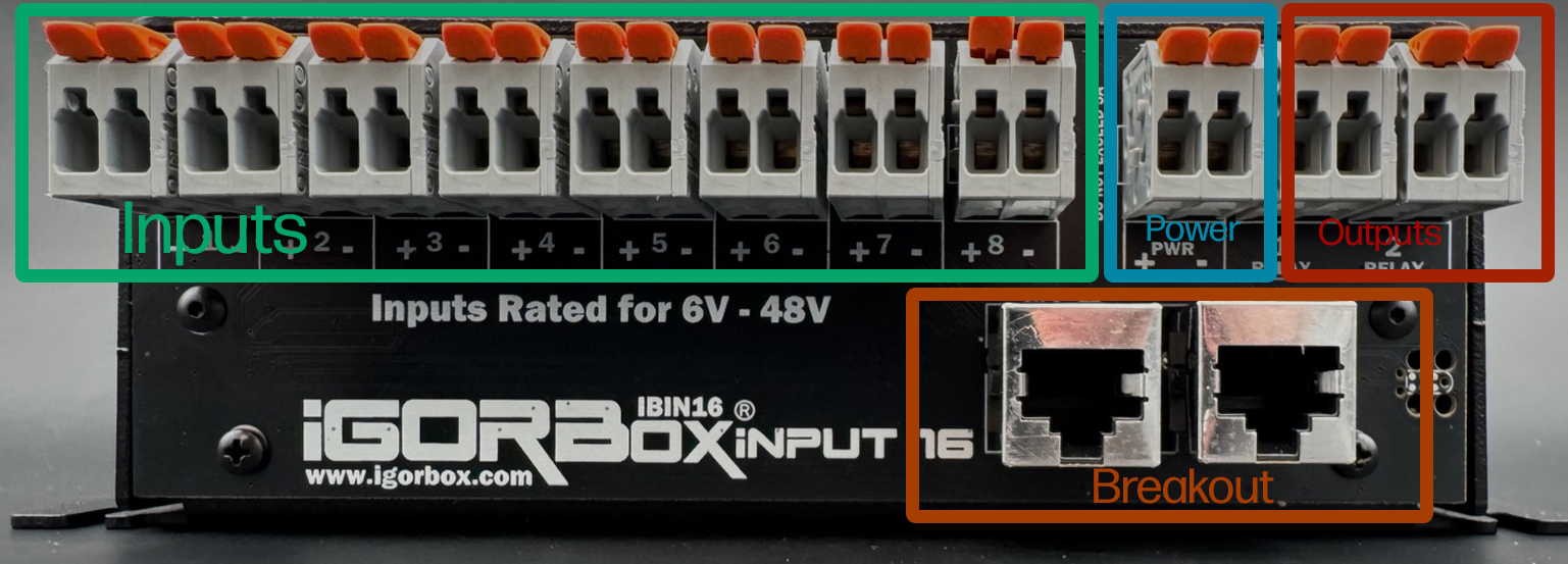
Each channel is a WAGO connector starting with channel 1 on the left and going to channel 8. These are optically isolated inputs and the polarity doesn't matter. They support 6–48V AC/DC. They are marked with a (+) and (-) but that's just a suggestion and not required.
The next WAGO (after channel 8) is the Power Output which is fed by the barrel jack you plug into the front of the controller. Positive is left and Negative is right. The helper LEDs indicate Red for Positive and Blue for Negative to help you identify this connector as well.
Then the last two WAGOs on the right are standard normally open relay outputs (1.5A each) that follow the same wiring conventions as the relay channels on the Output 8 MKII.
Under the row of WAGOs, you'll find 2 RJ45 jacks (Ethernet jacks). The left one is channels 9–12 and the right one is channels 13–16. Each jack connects to a channel breakout board. Two standard breakout boards ship in the box (one per jack) and carry the same 6–48V AC/DC requirement to activate. They are also not polarized.
Wiring inputs
Wiring a button
The simplest input — a push button or footswitch wired to a power source.
- Connect a voltage source's V+ through the button to one terminal of an input pair.
- Connect the same source's GND to the other terminal of that pair.
When the button is pressed, the input fires and triggers any Logic Rules bound to it.
Using the passthrough power
If your buttons are dry contacts (no voltage source of their own), you can use the controller's passthrough:
- Jump V+ from the passthrough zone to one side of the button.
- Wire the other side of the button to one terminal of an input pair.
- Jump GND from the passthrough zone to the other terminal of that pair.
Now the controller's own supply voltage drives the input, and the button is just a contact closure.
For escape rooms with lots of buttons close together, don't use the controller's passthrough — run a dedicated 12V or 24V supply for the button wiring. It keeps the wiring cleaner and gives you headroom if a wire shorts.
Wiring a magnetic / reed switch
Wire it exactly like a button. The magnet closes the contact, the contact closes the input. Polarity doesn't matter.
For escape room puzzle pieces, magnetic switches are usually the best choice — no moving parts to break, no debounce concerns, and the magnets are tamper-resistant.
Wiring an IR break beam
Most show-grade IR break beams have a switched output (open collector, contact closure, or 0/12V). Treat it like a button:
- For switched-output beams: wire as a contact closure with passthrough power.
- For active 0/12V output beams: wire the beam's output to one terminal and the beam's GND to the other.
The beam's V+ comes from your own supply (the beam's data sheet will tell you what voltage it wants).
Wiring a 24V industrial sensor
Industrial sensors (proximity, photo-eye, etc.) often need 24V to operate and output a 24V signal when triggered.
- Power the sensor from a 24V supply (its own, or your IgorBox's passthrough if you set the controller to 24V).
- Wire the sensor's signal output to one terminal of an input pair.
- Wire the sensor's GND to the other terminal.
Industrial sensors come in two switching types — you'll see them labeled PNP or NPN on the data sheet. Both work with the isolated input; if it doesn't trigger, just swap the two terminals.
Wiring an output from another controller
You can wire an output from any IgorBox controller (or any third-party show controller) into an Input 16 input. This is how you'd, e.g., have an Output 8 MKII fire an event that an Input 16 then routes through a Logic Rule.
If both boxes are IgorBoxes on the same network, you don't need to wire them together physically. Use a Logic Rule with a Named Trigger — that's how IgorBox controllers can talk to each other natively.
Wiring the relay outputs
The two onboard relay outputs work like the relay channels on an Output 8 MKII. Each pair is just a switch in your load's positive (V+) leg:
- Connect your power supply's GND to the load's GND.
- Connect the supply's V+ to one terminal of an output pair.
- Connect the other terminal to the load's V+.
When the channel turns on, the load turns on.
Common uses for the two relay outputs:
- Maglock release — wire the maglock's V+ through one of the relay channels and set the channel to Inverted in the controller's config in Studio. Inverting it energizes the relay at rest, so it behaves like a Normally Closed relay — and it "fails safe": if the controller loses power (a power outage at your venue), the relay drops out and the maglock unlocks. In normal operation: Logic Rule fires "puzzle solved" → channel activates → relay opens → maglock releases. (Maglocks are typically wired the opposite of "normal" — they're held closed by current and release when current is removed. So the inverse-on-release is what you want for fail-safe behavior.)
- Small effect or indicator — a low-power lamp, a buzzer, a single mister
- Trigger wire to another show controller — the relay closes a contact closure that the other controller reads as a trigger input
For loads above 1.5A, target an Output 8 MKII or LED Controller channel from your Logic Rule instead.
What you should not wire
- Mains AC voltage — even though the input range goes to 48V, this is for low-voltage industrial signals. Don't put 120V on the inputs OR through the relay outputs.
- More than 1.5A through the relay outputs — use the Output 8 MKII's bigger relays for higher loads.
- More than 48V on the inputs — you'll exceed the input's working range and damage it.